Angel is also certified in AutoCAD Civil 3D. A 3D CAD package that can read DXF files.

Intro To Coordinates Autocad Tips

Use Spherical Coordinates In 3d Autocad Drawings Autocad Tips Blog

What You Should Know About Autocad Coordinate Systems Dummies
Type 46 on the command line and press enter.

Absolute coordinate system in 3d cad. Smart Plant â 3D SP3D is a modeling software used in the engineering sector for pipe designing. That means that the physical movements of the machine are controlled by a computer via a complex mathematical coordinate system. Send a G90 command to tell your printer to use absolute positioning or a G91 for relative positioning.
3D Metrology Applications. The ability in your 3D CAD package to extrude the outline to create a 3D model. Generate detailed drawings with parts lists.
3D digital capture of shapes and surfaces using lasers is an effortless and precise process. This option is available only if the drawing file. The CNC process goes something like this.
Relative positioning is used when you want to tell the printer how far it should move from the current location. When entering those coordinates we can either enter absolute coordinate values. The LISP routine supplied here is an easy one.
Find new and used Coordinate Measuring Machines CMM for sale from suppliers near you. ABSOLUTE COORDINATE ENTRY. See quality control and inspection applications.
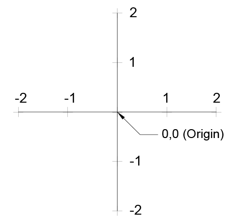
Absolute coordinate entry always counts from the origin. It tells numerically controlled lathes and machining centers how to move tools in order to perform various cutting operations. When you create or modify objects in a 3D environment you can move and reorient the UCS anywhere in 3D space to simplify your work.
If an origin point is not specified then the lowest and leftmost coordinate of the items selected is used as the origin. The OBJ file format is a simple data-format that represents 3D geometry alone namely the position of each vertex the UV position of each texture coordinate vertex. Improved Quality Control and Inspection.
Type L on the command line and press enter. Advance Steel 2021 AutoCAD 2021 AutoCAD Architecture 2021 AutoCAD Electrical 2021 AutoCAD MEP 2021 AutoCAD Map 3D 2021 AutoCAD Mechanical 2021 AutoCAD Plant 3D 2021. Imagine youre going to copy the outline and shift it in the Z dimension by some amount.
Verify dimensional accuracy and identify deviations from nominal CAD data during first-article and in-process inspection as well as inspection of incoming parts. The GLOBAL S coordinate measuring machine CMM delivers measurement productivity tailored to your workflow addressing the widest range of production requirements including throughput precision multi-purpose and shop-floor capabilities. Industrial 3D Laser Scanners Laser scanners play a key role in quality assurance.
Absolute positioning means that you will be telling your 3D printer to move an exact XYZ coordinate. Rotates the coordinate system in the current plane as selected by G17 G18 or G19. The file format is open and has been adopted by other 3D graphics application vendors.
Document your design with Product Manufacturing Information PMI and 3D sections. Coordinate Systems A particular kind of reference frame or system such as plane rectangular coordinates or spherical coordinates which use linear or angular quantities to. Auto cad 2D Objective type Questions and Answers.
The UCS icon changes automatically depending on the current visual style. Step 1 is the concept or idea stage Step 2 is the design or CAD process Step 3 is the. Such a manually made prototype can be converted into a 3D CAD file by using a 3D camera system.
Brown Sharpe Zeiss Mitutoyo and more. It uses coordinates 000 as the origin point which is the same as using the Paste to Original Coordinates option. Slicers are the easiest way to go from a 3D model to a printed part.
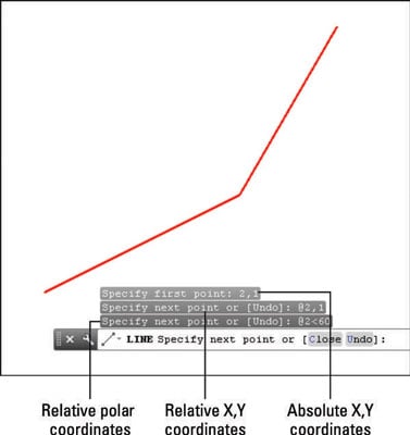
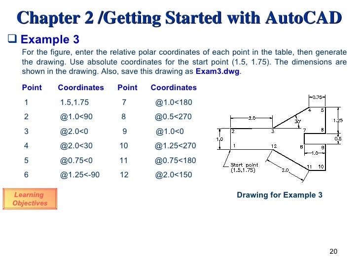
The common methods to enter coordinates in CAD is to enter X Y coordinate values in 2D drawings and enter X Y Z coordinate values in 3D drawings. It is equivalent to manual programming where each operation is spelled out line-by-line and is separate from M-code and T-code codes that control the machine and tooling. In 3D modeling of AutoCAD we examined the model of the Cartesian coordinate system or rather in the article 3D space in the Autocad and tied it to the Autocad system.
G-code is the operational language for CNC machining. Angel is also SafeLandUSA safety certificed and is an active member of the Geographic and Land Information Society. There are a few ways to control what that coordinate is.
Type 53 on the command line and press. Is a full service exact laser measurement company. Use computer-aided manufacturing CAM to program machine tools.
3D Carving for the Absolute Beginner Part 9. Express 14 2644 2649 2006. Multisoft Virtual Academy conducts SP3D online training for engineering candidates with an interest in the CAD domain and aspiring to establish a career in pipe designing.
With a deep understanding of ESRI standards with reference to multiple Geographic and State Plane coordinate systems Mr. Share your project for review and markup in the Solid Edge Portal. The R parameter is added to the existing rotation instead of being absolute.
OBJ or OBJ is a geometry definition file format first developed by Wavefront Technologies for its Advanced Visualizer animation package. Absolute coordinate entry is the default. When drawing lines AutoCAD is ready to place the next vertex wherever you tell it to go.
An objective type quiz which can be attempted to check enhance your CAD knowledge. Extrusion is a pretty easy concept to grasp. The UCS is useful for entering coordinates creating 3D objects on 2D work planes and rotating objects in 3D.
A computer moves the. Publish illustrated work instructions operations manuals and parts catalogs. Yau High-resolution real-time 3D absolute coordinate measurement based on a phase-shifting method Opt.
In addition to selling CT Scanners and performing CT contract services on-site or in-house we provide contact Probing Digitizing and non-contact 3D Scanning measurement on. Image courtesy of Absolute Wire EDM. A coordinate system in which the locations of points in space are expressed by reference to three perpendicular axes called the coordinate axes xyz.
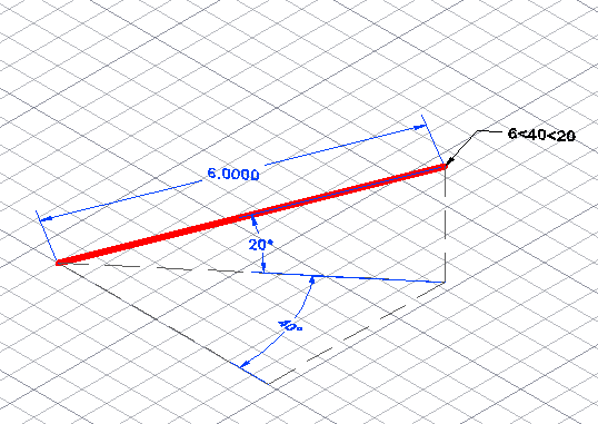
The start of every engineering process begins in the world of CAD. In addition to these the CAD system also provides polar coordinates cylindrical coordinates spherical coordinates. Understand the UCS in 3D.
Dear readers these Auto cad 2D Multiple choice Questions have been designed specially to get you acquainted with the nature of questions you may encounter during your Job interview for the subject of Auto cad 2DAs per my experience good interviewers hardly plan to ask any particular question during your Job interview. A rectangular coordinate system is a rectilinear coordinate system with mutually perpendicular axes on a plane or in space. Displays coordinates relative to the geographic coordinate system specified for the drawing.
Engineers will make either a 2D or 3D drawing. Test your ability and CAD skills for free by taking this online CAD quiz. Trained in the use of Trimble TerraSync GPS Pathfinder as well as other GIS software Mr.
These programs import a CAD model. The industry uses laser scanners primarily for the quality control of geometries and surface but also for reverse engineering fit and finish and assembly applications.
Coordinate Systems In Autocad The Cad Masters

Pdf Compare Between Methods Of Entering Coordinate System Absolute Relative Polar In Autocad

Using The Coordinate System In Autocad Youtube
Autocad Coordinates System

April 2020 Informational Encyclopedia

Autocad Introduction

Working With Relative Cartesian Coordinates Autocad Cad Cam Engineering Worldwide

Autocad And The Cartesian Grid Free Autocad Tutorials
